Optimizing UHF RFID Technology for Asset Tracking and Management

In industrial manufacturing, successfully leveraging ultra-high frequency radio-frequency identification (UHF RFID) technology for asset tracking can significantly enhance operational efficiency and productivity. The ability to reliably track and manage valuable assets, such as press dies, casting molds, and other tooling, is crucial. However, the performance of UHF RFID systems is influenced not only by the technology itself but also by the industrial environment in which it operates. In this post, I explore the critical factors within industrial settings that affect UHF RFID functionality and provide strategies for overcoming these challenges.

Metal surfaces in manufacturing settings can severely disrupt UHF RFID signal integrity, leading to poor tag readability or possibly, even unintended tag reads. Metal can reflect, attenuate, or fully block RFID signals. To counteract these effects, focus on selecting the proper tags, choosing and mounting antennas, and setting up the system correctly with both software and hardware.

Tag selection and mounting

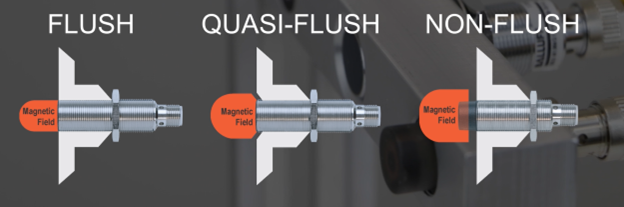
Proper tag selection and mounting are crucial for optimizing UHF RFID system performance. Tags should be chosen based on their compatibility with the materials they will be attached to, such as metal or plastic since different surfaces affect signal reception differently. Tags are designed for installation on metal or with a clearance zone and vary in size, which plays a critical role in the maximum readable distances. Strategic mounting of tags is essential to minimize direct interference, and they should be positioned and oriented to maximize exposure to reader antennas. Adhering to these general guidelines, along with any tag-specific guidelines ensures higher read rates and improved efficiency in asset tracking.

Adapting to environmental conditions

The rugged nature of industrial environments, including extreme temperatures, humidity, and chemical exposure, requires robust RFID solutions. Tags and antennas must be specifically selected for their durability and resistance to harsh conditions. In high-temperature environments, for example, specialized tags and housings can tolerate up to 220°C (428°F) but must cool down to lower temperatures before they can be read or written to effectively without damaging the tags.

Strategic placement of reader antennas and power settings

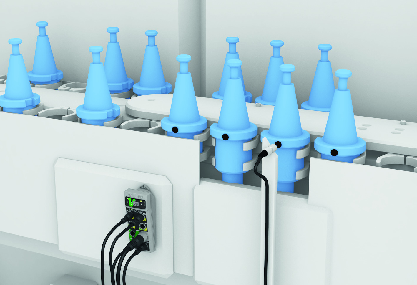
Proper placement of RFID reader antennas is vital to prevent physical obstructions from blocking or weakening signals. Optimal antenna placement, coupled with the use of multiple antennas at various orientations, significantly enhances the system’s ability to capture data, even in challenging industrial environments. Also, it’s crucial to consider power settings. Using power settings that are too high, for example, could lead to unintended tag reads, causing confusion in the tracking system.

Site surveys and feasibility studies

For newcomers to UHF RFID applications, it is advisable to consult with professionals. Initial site surveys can help determine the feasibility of an application. If viable, a subsequent feasibility study can determine the selection of antennas, processors, and tags. This study also establishes the overall topology, physical locations, distances, angles, and optimal power settings in the actual installation environment.

Implementing UHF RFID technology in industrial settings offers substantial benefits for asset management but requires careful consideration of environmental factors that could impede its performance. By understanding and mitigating issues related to metal surfaces, product selection, and harsh environmental conditions, manufacturers can fully leverage UHF RFID technology to streamline operations and enhance efficiency. RFID technology can become a cornerstone of modern manufacturing automation strategies through strategic system design and ongoing performance evaluations.

Choosing Between Color and Monochrome Cameras for Machine Vision

If you’re using machine vision cameras, you’re most likely looking at as much detailed information as quickly as possible from your captured images. While some cameras can detect wavelengths beyond what our eyes can see (UV and IR), many applications focus on the visible range. So, how do you decide whether to use color or monochrome cameras for your vision application?

Sorting and grading by color

Typical uses of a color sensor include simple color grading and sorting products by color. It’s handy for sorting pills, labels, textiles, and paints according to their colors.

Color cameras use the same types of vision sensors as monochrome cameras, except their pixels are covered by either red, blue, or green filters. These filters help identify the colors present in the image by separating them based on wavelengths. The Bayer color filter, commonly used in color cameras, has twice as many green filters as red or blue ones.

Adding these filters decreases the number of electrons that ultimately reach the silicon and can be measured. Typically, adding these filters leads to a decrease in quantum efficiency of about 5-10% compared to an equivalent monochrome sensor.

Effects of color interpolation on image quality

In addition to dimming with a color filter, color interpolation creates a full-color image after processing by blending adjacent pixels. This typically results in resolution and sensitivity that is generally lower than monochrome image sensors of the same pixel count and size. Therefore, it’s advisable to use color image sensors only when color information is required for the application. [1]

Additionally, the color captured by your sensor can be influenced by the color of the wavelength of light you are applying to the subject. Carefully integrate and maintain lighting conditions to achieve the best image quality.

Unless you are doing a comparison that will be determined/confirmed and evaluated exclusively by color, a monochrome camera typically provides quicker and more accurate information.

Your choice between color and monochrome cameras depends on your project’s specific needs. While color sensors are great for tasks like sorting by color, they may sacrifice some resolution and sensitivity. Considering factors like lighting conditions and the necessity for color information will help you make the best choice for efficient and accurate image analysis.


[1] Sony Semiconductor Solutions Corporation

Digitalizing Manufacturing: Work Instructions and Sensor Feedback

Digital work instructions are becoming a game-changer in the increasingly fast-paced manufacturing world. They offer many benefits that enhance efficiency, reduce errors, and foster collaboration.

The digital advantage

Digital work instructions offer real-time updates, ensuring that all operators can access the latest version, even across various production facilities. This eliminates costly mistakes caused by outdated instructions or checklists.

These instructions are often part of larger workflows or Standard Operating Procedures (SOPs). Digital solutions can enable the seamless initiation of related procedures. For instance, if an operator identifies a machine issue, they can launch a workflow directly from the system for other team members or external workers.

Seamless integration

Digital work instructions integrate with planning systems, providing real-time visibility into expectations. Integrating ERP, MES, or LIMS systems allows data exchange and automated report generation.

Interactive feedback

Digital work instructions facilitate responsive interactions, unlike paper-based ones. When a threshold value is exceeded, the system can immediately alert the operator, who can notify supervisors or promptly follow additional instructions.

Automatic logging

Digital systems automatically record executed procedures, providing invaluable for compliance audits and continuous improvement initiatives.

Visual enhancement

Work instructions are often enhanced with multimedia elements such as images, videos, or 3D models. These visual aids enhance communication and comprehension and often reduce operator errors.

The future of manufacturing: sensor feedback

Sensors provide live data on equipment performance, environmental conditions, and safety parameters. This allows operators to receive immediate feedback for proactive adjustments, timely preventive actions, and “predictive maintenance” by monitoring wear and tear. Predictive maintenance helps schedule maintenance before critical failures occur, minimizing downtime, extending equipment lifespan, and ensuring efficient use of resources.

Additionally, sensors can detect deviations from optimal conditions, enabling operators to promptly address issues and maintain consistent product quality.

In conclusion, digital work instructions streamline processes, foster collaboration, and empower operators. When integrated with sensor feedback, businesses can gain efficiency and accuracy and, for a moment, enjoy that ever-elusive competitive edge in today’s rapidly evolving business environment.

Choosing the Right Code Reader: Laser Versus Vision

When choosing a barcode reader, the first step is to select between vision-based or laser-based reader options. Each option has its own pros and cons that are worth considering. Assuming that the goal of any code reader is to maximize read rate and minimize errors, it’s easy to evaluate each technology separately.

Laser-based readers 

Laser-based readers use a red laser diode and a rotating mirror to scan each barcode and create a raster image, like how old CRT TVs would display an image on the TV screen. You may remember this from older grocery store checkouts, where red laser lines projected up through a transparent glass pane. One obvious disadvantage of this is that operators don’t typically enjoy dealing with lasers, as no one likes getting a laser to the eye, even if it’s a low-energy laser device.

Another, maybe less obvious, disadvantage is that these rotating mirrors can present a common failure mode, especially in applications with high shock or vibration.

So why choose a laser scanner? The answer lies in its depth-of-field capability. Laser readers out-perform their vison-based counterparts in extremely short ranges (less than 1-2″ from the sensor face) and when the distance from the sensor to the code varies by more than about 3 feet. In these cases, the rotating mirror and highly coherent laser can improve read rates.

Vision-based readers

Now, let’s turn our attention to vision-based readers. These function just like any regular camera, but their image processing methods are what make them interesting. They snap pictures at high speeds and use vision algorithms to find and decode barcodes. One significant advantage is the simplified alignment and setup, as you can see exactly what the code reader sees during the setup process.

Modern code reading algorithms enable not just 1D codes but also 2D, Datamatix, QR, and many other symbologies that 1D readers can’t read. Moreover, vision-based readers can interpret codes regardless of their rotation or orientation. Additionally, vision-based readers offer added benefits for code quality assessments and auditing. Pictures of the product and codes can be sent over the network and saved for later review. Quality algorithms can assess barcode grades and identify damage and print quality issues, while advanced reconstruction can read even severely damaged codes.

Considering these factors, vision-based readers will often emerge as the logical choice, especially given the explosion of new product releases in recent years. With all this new development, there has also been considerable progress made in standardizing code-reader communications. Many vision-based readers now support a growing consensus of open standards. There are ethernet-based options supporting REST and MQTT, as well as IO-Link devices for remarkably easy installation and integration into existing machines and standard sensor architectures. This level of compatibility is not easy to find in an old laser-based reader.

Flush, Non-Flush, or Quasi-Flush: Choosing the Right Proximity Sensor for Optimal Object Detection

Proximity sensors are aptly named for their ability to detect objects in close proximity. They are not suitable for detecting objects across a room or on a conveyor belt. Their focus is on detecting objects up close and personal. Inductive proximity technology allows detection from physical contact with the sensor head to a few millimeters away. When choosing the right type of inductive proximity technology, several factors must be considered. Let’s start at the beginning.

Inductive proximity sensors may seem magical, but they operate based on specific magical characteristics. To prove my point, show them (and try to explain them) to a kid. Imagine an invisible electromagnetic field surrounding the sensors. This field can only be disrupted by a metal target. Different metals can affect this field at varying distances, depending on the type of metal and the sensor used. In simple terms, the sensor can detect if an object is a metal and, to some extent, the type of metal– all without touching the object physically.

Now that we’ve covered the basics, let’s focus on understanding the characteristics of the magical electromagnet field, its impact on sensing range, mounting, and the risks of sensor and/or part damage.

You may have heard the terms flush or non-flush used for inductive proximity sensors. I’ll throw one more into the mix: quasi-flush.

Non-flush mounting

Non-flush mount proximity sensors offer the longest range – the air gap between the target and the sensing head. This can be a good thing or a bad thing, depending on the situation. For precise positioning requirements, the extra range might cause issues. However, if precision is unnecessary, the extended ranges could be beneficial as objects might come into range slightly differently. One major downside of non-flush sensors is their susceptibility to damage. Typically, several millimeters to half an inch of the sensing head is exposed, increasing the risk of shearing off the sensor head or damaging the object you are detecting.

Flush mount proximity

With flush-mount proximity, you gain some protection for both the sensor head and the object being detected, but it comes with a trade-off of reduced sensing range. This is because the shape of the electromagnetic field coming out of the sensing head is focused to avoid triggering the mounting block or other hardware.

Quasi-flush mounting

If you are looking for a Goldilocks solution, consider quasi-flush mounting. With this style of sensing head, you recess the sensor into a mounting block, which helps focus the electromagnet field a bit more, thereby adding more field length compared to a flush mount. It is important to ensure your mounting block has a bevel around the sensing head to avoid false triggers of the output.

So, when deciding which type to use, I recommend using flush or quasi-flush sensors for any target that may come into contact with the sensing head. This choice will prolong the sensor’s life and better ensure proper target triggering. Non-flush sensors are great when you need a larger gap between the target and the sensing head, and precision is not a big issue.

In closing, proximity sensing is designed to be a non-contact form of object detection, specifically metal objects. The goal is to avoid any contact with the sensing head, although we’re aware that object/sensor collisions can happen.

Exploring RFID Frequencies: Understanding Variations and Applications

Radio Frequency Identification (RFID) is a great way to track all kinds of data throughout a plant—from the location of a part in the facility to the operations that have been performed on a specific part. When choosing an RFID solution, there are three classifications to consider, and the positives and negatives of each may determine the best solution for each individual application. Low, high, and ultra-high frequencies are the terms we use to talk about the different ranges of frequencies given in hertz.

Low Frequency (LF)

LF RFID is typically in the range of 70 KHz- 455 KHz. It is immune to external interference in the direct surrounding area with a range of under 100mm – the shortest distance of the three frequencies. One common application is tracking tool life and usage inside tool cribs. especially where coolant and lubricant are in abundance. LF RFID is also seen at the entrance of facilities that will lock and unlock doors using RFID tags and for tracking livestock, such as cows with ear tags.

High frequency (HF)

HF RFID sits at 13.56 MHz and primarily serves for high-speed data tracking, along with handling high data volumes. It offers a greater range than LF RFID but is still not the furthest-reaching option. HF is a great tool when paired with numerous components that require tracking along conveyor systems or between robotics cells. The high speed allows for the reading and writing of data from embedded tags on products passing by the antenna. This increases the speed at which a tag can pass by and ensures accurate data transmission at a significantly faster rate compared to LF. For instance, in tracking engine blocks along an assembly line, by mounting an RFID HF tag and updating its data at each station, you can confirm the completion of the processes from each location sending out the product.

Ultra-high frequency (UHF)

UHF operates within the frequency range of 860 and 960 MHz, offering a reading distance of up to 12m, which varies depending on the size of the antenna. UHF operates using backscatter allowing it to recognize and read multiple tags simultaneously. UHF has the highest range of reading and writing to and from the data tags. However, it is also the most sensitive to its surrounding environment, necessitating an application feasibility study to ensure proper placement of the antenna and tags. Common applications for UHF include logistical tracking of on-site vehicles like forklifts between different company sectors, as well as inventory and pallet traceability.

RFID technology is essential for data tracking in industrial settings, offering insights into operations and inventory. Understanding frequency distinctions is key, as each range has unique advantages and limitations. Ultimately, choosing the right solution depends on factors like range, speed, and environmental conditions. By evaluating these, you can optimize processes and efficiency with RFID technology.

Using Ultrasonic Sensors in Microwell Environments

Ultrasonic sensors offer unique capabilities for lab environments. They rely on ultrasonic waves to detect part presence with precision. In this blog, I explore the workings of ultrasonic sensors, their applications, and considerations for optimal implementation, shedding light on their pivotal role in automating lab processes.

Understanding the functionality

Let’s first touch on how ultrasonic sensors function in different working environments. Ultrasonics refers to vibrations of frequencies greater than the upper limit of the audible range for humans, that is, greater than about 20 kilohertz. Ultrasonic waves of extremely high amplitudes are known as sonic. The sensors consist of both a transmitter and receiver, detecting part presence by measuring these sonic waves. The normal sensing range of an ultrasonic sensor varies depending on the specific model and application, typically spanning from a few centimeters to several meters. When working in a lab environment that relies heavily on accuracy and efficiency, ultrasonic sensing technology might be a valuable option for your operation.

Ultrasonic applications to enhance lab processes

So, how are ultrasonic sensors used in lab environments, and what applications are they used for? Most commonly, laboratories use them in a microwell environment. They can measure various processes, such as mixing, homogenization, dispersion, emulsification, extraction, degassing, and sonochemical reactions. The specific application dictates the preference for ultrasonic sensors. However, high-frequency ultrasonic sensors generally precede smaller objects and fine detail resolution, typical requirements in microwell environments.

Let’s focus more in-depth on mixing, homogenization, and cell lysis applications. Ultrasonic waves, with their high-frequency vibrations, can disrupt cell membranes, releasing intracellular materials, a process that can be useful in biological and medical research. Additionally, in microwell plate reading, ultrasonic waves can ensure a uniform distribution of particles or cells within the wells. Ultrasonic sensors equipped with an attachment like a cone or a similar apparatus focus the waves, which can improve accuracy in these environments. If you are having trouble measuring or automating any of these applications, an ultrasonic sensor can be a viable solution.

Considerations before using ultrasonic sensors in labs

Before deciding on an ultrasonic sensor, it is important to have a comprehensive assessment of variables in your application, like the frequency and intensity of the ultrasonic waves, the design of the microwell plate, and the nature of the material or cells within the microwells. This will ensure a successful integration and operation of the ultrasonic sensors with your application.

Despite these considerations, ultrasonics play a key role in automating lab cell environments, especially when capacitive or photoelectric sensors are not viable options.

For further insights tailored to your specific application, try reaching a trusted consultant or manufacturer.

Unlocking Industrial Sensor Potential in the IIoT Era


In the dynamic landscape of the Industrial Internet of Things (IIoT), one cannot ignore the pivotal role of industrial sensors in revolutionizing manufacturing processes. As we navigate this era of unprecedented connectivity and data-driven decision-making, the true potential of industrial sensors becomes increasingly evident, offering a myriad of benefits to industries worldwide.

Eyes and ears of smart factories

At the heart of this technological renaissance, industrial sensors function as the eyes and ears of smart factories, creating a symphony of data that empowers manufacturers to optimize operations, enhance overall efficiency, and increase profits. The advent of IIoT has amplified the capabilities of these sensors, turning them into indispensable assets for organizations aiming to stay ahead in the competitive industrial landscape.

Imagine a manufacturing floor where every piece of machinery seamlessly communicates with each other, providing real-time data on performance, status, and potential issues. This interconnected ecosystem is made possible by the deployment of advanced industrial sensors and advanced analysis systems. These devices are not merely passive observers; they are the linchpins of a connected industrial infrastructure, facilitating predictive maintenance, reducing downtime, increasing profits, and saving costs.

Real-time data for optimal efficiency

One primary advantage of industrial sensors and systems in the IIoT era is their ability to gather massive volumes of data. This influx of information allows for comprehensive analysis, enabling manufacturers to identify patterns, detect anomalies, and make informed decisions. Predictive analytics powered by industrial sensors transform reactive maintenance into a proactive approach, preventing equipment failures before they occur and ensuring seamless production processes.

Predictive maintenance

Moreover, integrating artificial intelligence (AI) and machine learning (ML) algorithms with industrial sensors takes predictive maintenance to the next level. These intelligent systems can learn from historical data, adapting to changing conditions and continuously improving their accuracy. The result is a finely tuned predictive maintenance strategy that not only minimizes downtime but also extends the lifespan of machinery, optimizing return on investment.

In the IIoT landscape, security is paramount. Industrial sensors, when harnessed correctly, contribute to building robust cybersecurity frameworks. As data flows between devices, encryption protocols and secure communication channels safeguard against potential cyber threats. This initiative-taking approach ensures the integrity of sensitive information and protects against unauthorized access, a crucial aspect in an interconnected industrial ecosystem.

Driving the next industrial revolution

The IIoT era has unshackled the true potential of industrial sensors and systems, transforming them from passive observers to proactive catalysts for innovation. As we continue to explore the boundless possibilities of connectivity and data-driven insights, industrial sensors stand as the unsung heroes, driving the next industrial revolution and ensuring a future where efficiency, sustainability, and competitiveness converge seamlessly on the factory floor.

Rotary Encoders: Precision Positioning One Rotation at a Time

Often, some of the most important automation sensors are the ones people know the least about or may not even realize they need for their applications. One of those sensors is the rotary encoder, which every industry uses to provide mechanical values for rotation angles and convert them into electrical signals to help you position all critical machine parts with high precision. The robustness of rotary encoders enables many uses even under extreme conditions, such as in food processing, machining processes, automotive component assembly, conveyor systems, and packaging equipment. Many vision systems in use today for inspection also require an encoder input for inspecting objects on the move.

The two main types of rotary encoders are incremental encoders and absolute encoders. Here’s a quick look at why you would choose one over another and some key characteristics.

Incremental encoder features

    • High-resolution angle measurement
    • High shaft load, up to 500 N
    • High protection classes for harsh environments, up to IP69K
    • Corrosion-resistant designs with stainless steel housings are available
    • Available interfaces, such as ABZ, sin/cos, TTL, and HTL
    • Optical technology for precise, high-resolution measurements or magnetic technology for use in harsh environmental conditions is available

Incremental encoders for speed monitoring and position determination

Incremental encoders compare machine data to the last data collection point and record it. Each time the machines and the encoder are switched on, they define reference values. Incremental encoders output a precisely defined number of pulses per revolution. The signal serves as a measure of the angle or distance covered. The more signals are output per revolution, the higher the resolution of the incremental encoders and the more precise the measurement and control of your system. With incremental encoders, you can monitor and reliably control the rotation and belt speed of your machines and systems. Some incremental encoder interfaces include ABZ, sin/cos, TTL (Transistor-Transistor Logic), and HTL (High Threshold Logic), which meet common and established industry interface requirements.

Absolute encoder features

    • Needs no homing run (they always know where they are)
    • No data loss in case of power failures
    • Corrosion-resistant designs with stainless steel housings are available
    • Robust design for harsh environmental conditions
    • Available interfaces, such as RS485, SSI, and CANopen
    • Available as single-turn or multi-turn encoder
    • Optical for precise, high-resolution measurements or magnetic for use in harsh environments

Absolute encoders for high-precision positioning and data acquisition

Absolute encoders detect positions and, unlike incremental encoders, assign a unique value to each signal. You know where your machines are at any moment, even during a power failure. Absolute encoders do not require a reference value or a homing run each time the machine is switched on, so your machine data is not lost to the encoder when switched off. You can monitor and reliably control the rotation and belt speed of your machines and systems. Some interfaces offered for absolute encoders include RS485, SSI, and CAN open, which meet common and established industry interface requirements.

Consideration for precision, robustness, and compatibility

When you start to configure either your incremental or absolute encoder for your application needs, there are some other characteristics to consider, such as single-turn or multi-turn for more precision. Optical or magnetic encoder for either high precision or robustness for harsh environments. The encoder housing needed standard or stainless steel for wash-down areas. For your mechanical connection point, you will need to determine your shaft diameter and flange style. These may seem like a lot of options, but encoder manufacturers offer simple selection guides to ensure you choose exactly what you need for your application.

As you become more aware of the many different types of automation products, don’t forget the rotary encoder if you need some precise positioning or speed measurement on your next application.

Automation, Networking and Sensors in Intralogistics

The intralogistics industry has made significant investments in automation since 2020. The boom in ecommerce, accelerated by the pandemic, pressured online retailers to improve their warehouse operations through automation. Traditional manufacturers and non-ecommerce (B2B) firms have been slower in automating their intralogistics operations, and penetration is still relatively low. This is rapidly changing, driven by market factors such as labor issues, product individualization, supply chain challenges, higher efficiency/productivity/quality, faster delivery, and wider adoption of ecommerce by B2B firms.

The deeper penetration of automation in intralogistics means that the applications are now using or adapting many of the same technologies and smart manufacturing processes employed in traditional manufacturing: robotics, PLCs and motion controllers, industrial networks, sensors, motors and drives, RFID/code reading, vision systems, human-machine interfaces, automation software, IIoT/Industry 4.0, and more. This blog focuses on the use of sensors, networking, and RFID/code reading in common intralogistics processes:

    • Conveying and transporting
    • Storage and retrieval
    • Sorting and picking

Within these areas, there are several key applications. I’ll go into more detail on solutions for each of them:

    • Object detection
    • Controls architecture
    • Traceability
    • Condition monitoring

Object detection: Photoelectric, inductive, ultrasonic, and capacitive sensors are used to reliably detect objects on conveyors, container fill levels, and object presence, position, shape, color, distance, or thickness. Photoelectric sensors are often used to detect bottles, totes, or material on conveyors or to detect items in racks or on transporters. Inductive sensors can detect metal objects on conveyors or in racks, but also the position of parts of the equipment to verify position, alignment, or proper operation. While photoelectric or inductive sensors can also detect objects for picking and sorting applications, vision systems are often used when robots are involved in the process.

Controls architecture: Connecting sensors and devices to the control system can be time-consuming and complicated, involving long cables, many terminations, and difficult troubleshooting. The automation industry, therefore, uses industrial networking to simplify controls architectures. It is an especially interesting and cost-effective approach for intralogistics because the facilities are often large, with long distances and many sensors. Network blocks and hubs using technologies such as IO-Link make it easy and inexpensive to connect many sensors using common M12 or M8 cables. IO-Link not only gathers standard process data but also provides diagnostic/event and parameter data. This simplifies detecting the individual device status and troubleshooting mistakes in wiring or broken sensors.  When implementing automation, especially for large-scale conveying or storage and retrieval systems, companies typically apply a networked controls architecture across most intralogistics processes.

Traceability: Tracking the movement of goods through a facility is a critical part of the intralogistics process. The most used technologies are RFID and code reading; selection depends on the application. RFID is generally available in low (LF), high (HF), and ultra-high (UHF) frequencies. LF and HF RFID are good for short-range part tracking and production control where data needs to be read/written to a single tag at a time (for example, items on a conveyor). UHF RFID systems are better for longer distance detection of multiple tags (for example, tracking pallets through a facility). Coder readers are popular in intralogistics facilities because bar codes are common, simple, and easy to use. Reader technology has evolved to address past challenges such as reading multiple codes at once, imprecise code location, and code type variation. In some cases, companies use code reading for positioning storage systems or navigating AGVs.

Condition monitoring: Reducing unplanned downtime and improving Overall Equipment Effectiveness (OEE) are focus topics in intralogistics automation, and condition monitoring offers a solution to these challenges. A wide variety of sensors are available to detect vibration, temperature, pressure, flow, and humidity to help monitor equipment conditions. This sensor data can be easily gathered through the controls architecture or “add-on” data gateways, with IO-Link offering a wide variety of sensor and gateway choices. The most common intralogistics condition monitoring applications involve motion (motors, gearboxes, bearings, shafts, pumps, fans) for conveyors, storage/retrieval, and transport systems.

The use of automation in intralogistics will continue to grow rapidly as both ecommerce firms and traditional manufacturers seek to optimize their warehouse, conveying, and picking/sorting operations in response to industry and societal trends. These companies are realizing that worker shortages, faster delivery, improved quality, higher efficiency, mass customization, and supply chain issues are best addressed by automation.